CHAPTER 23. Mechanical Circulatory Support Devices in Transport
Leslie C. Sweet and Allen C. Wolfe Jr.
Competencies


1. Identify the indications for the use of a mechanical circulatory support device.
2. Perform an assessment of the patient with a mechanical circulatory support device.
3. Manage specific mechanical circulatory support devices before, during, and after the transport process.
The pace of technologic advances over the past several decades has been dramatic. Concurrently, the healthcare industry has revolutionized its technology, becoming smaller, faster, more efficient, and more sophisticated. The continued improvements in patient outcomes and the public’s expectation for state-of-the-art medical care continue to propel healthcare technology into the 21st century. The rapid explosion of research in healthcare technology has hastened patient recovery and return to the community. In earlier decades, the prehospital healthcare providers’ primary concerns with technology were automatic implantable cardioverter defibrillators (AICD) and insulin or vasoactive medication pumps. In regards to heart failure, cardiac assist devices have dominated the first decade of the 21st century, similar to how the cholesterol-lowering drugs, statins, dominated the 1990s. Although the devices were in development for many decades, the evolution of cardiac assist devices seemed slow. With new technologic advancements and clinical understanding of engineering designs, the field of mechanical circulatory support has exploded.
HISTORIC PERSPECTIVE
In 1966, Dr Michael DeBakey implanted the first successful cardiac assist device in a female patient in her mid-thirties who had failure to wean from cardiopulmonary bypass (CPB). The patient was successfully supported by the device for a total of 10 days12; the device was then explanted, and the patient was ultimately discharged home. This landmark success fueled the race for widespread use of mechanical circulatory support devices for severe end-stage heart failure. Subsequently, the primary focus of researchers and physicians turned to total replacement of the injured myocardium with the use of a total artificial heart (TAH). In 1969, Dr Denton Cooley implanted a TAH, the Liotta Heart, in a patient with failure to wean from CPB. The patient was supported for 64 hours before undergoing cardiac transplant. The groundbreaking use of this device perpetuated further advances in the use of TAH and assist device technology. Additional modifications and clinical use continued into the 1980s with the first permanent implantation of a TAH in 1982 into an elderly dentist, Dr Barney Clark, at the University of Utah by Dr William Devries. The device, the Jarvik-7 TAH, was designed by Dr Robert Jarvik and associates for total cardiac replacement. Although Dr Clark ultimately died of multiple complications, he was fully supported for an unprecedented 112 days by a TAH without any native ventricles in place. 8,12 This mechanical circulatory support of a human for nearly 4 months was a pivotal achievement for the field of artificial organs. The Jarvik-7 has undergone further advances and is currently known as the CardioWest temporary TAH (SynCardia Systems, Inc, Tucson, Ariz). Limitations of the earlier technology, however, did prompt scientists and physicians to rethink whether assisting the heart, versus replacing it, may be more appropriate when feasible. 12
In the 1980s, while heart transplantation gained prominence in the cardiac surgery arena, many end-stage heart failure patients died awaiting transplant due to an insufficient number of donor organs comparable to the profoundly increasing number of waiting transplant candidates. 1 In light of this skewed supply-demand ratio, medical researchers and engineers were tasked with developing a mechanical circulatory support device readily available and capable of sustaining patients as a bridge to transplant until a suitable donor organ became available and capable of providing lifetime support to patients with chronic heart failure deemed ineligible for heart transplant. The mid 1980s brought significant progress in the successful uses of ventricular assist devices (VADs) in patients awaiting heart transplant. Dr Phillip Oyer at Stanford University Hospital implanted a Novacor left ventricular assist system (LVAS; WorldHeart, Inc, Audubon, Pa). 17 This was followed in the early 1990s by other successful uses of VADs, including Dr Robert Kormos and colleagues at the University of Pittsburgh who developed a program to allow the discharge of patients with VADs into the community. 12 These significant and successful uses with VADs as a bridge to transplant lead to the groundbreaking Randomized Evaluation of Mechanical Assistance for the Treatment of Congestive Heart Failure (REMATCH) trial to evaluate the use of the HeartMate VE LVAS for long-term cardiac support. Approved by the US Food and Drug Administration (FDA), the REMATCH trial was a multicenter clinical trial designed to compare optimal medical management (OMM) with long-term HeartMate VE LVAS support in patients with severe, medically refractory, end-stage heart failure deemed ineligible for cardiac transplant. The trial showed that the VE LVAS significantly improved long-term survival and quality of life in this very ill patient cohort. Although the VE LVAS outperformed the OMM strategies in the REMATCH Trial, the trial results still raised doubts with critics regarding the durability and infection-related complications of the left ventricular assist device (LVAD). 12,19 With the increased cost of LVAD patient management within the hospital setting, caregivers began to look to the management of these patients in the community. The goal of successful discharge of patients into the community was profound improvement of patient quality of life and survival with proper support, education, and training.
Concurrently, the development of the intraaortic balloon pump support began in 1958 when Dr Dwight Harken described a method to treat left ventricular failure with counterpulsation. His recommendation was removal of a certain amount of blood volume from the femoral artery during systole and rapid replacement of this volume during diastole. 15 Complications arose because of the need for bilateral arteriotomies of both femoral arteries and hemolysis of cells in the pumping apparatus. 15 This procedure necessitated surgical insertion and surgical removal, which increased the potential for postoperative complications. Later, at the Cleveland Clinic, a researcher in the 1960s named Dr Spiro Moulopolous, developed a form of treatment for left ventricular failure that expanded significantly in the years that followed. 4 With the concepts of his predecessors, he used what is today known as the intraaortic balloon pump (IABP) in three patients with cardiogenic shock. He made the simple, effective, and affordable circulatory assist device to support this challenging patient population. 9 The groundbreaking research gave rise to other great work at that time. Dr Adrian Kantrowitz in 1968 continued to work with counterpulsation and showed 27 patients with cardiogenic shock with both hemodynamic and clinical improvement. The cardiogenic shock was able to be reversed. 4 The evolution of all of these mechanical circulatory support devices (MCSDs) has created a more sophisticated set of treatment strategies to offer today’s complicated patient cohort that is supported with both air and surface transport.
THE BASICS
Mechanical circulatory support devices (MCSDs) are mechanical devices or pumps designed to support the pumping function of a failing heart, whether attributable to acute cardiogenic shock or severe chronic cardiomyopathy. These devices may be separated into two major categories: total artificial hearts (TAHs) and ventricular assist devices (VADs). A TAH is a device that completely replaces the native heart physically, not just functionally. Implantation of a TAH involves removal of the native heart similarly to cardiac transplantation. Typically, the great vessels of the heart remain intact as does the atria, with complete excision of the remaining heart muscle. The TAH is then attached to the remaining atrial cuffs and great vessels. A caveat of a TAH is that if the device should fail no “back-up” native heart exists for compensation. In addition, because of the inherent size of a TAH, the patient must have adequate thoracic space to accommodate the pump. Total artificial hearts are most ideally suited for patients with biventricular heart failure (BVF), with both the left and the right ventricles having severe medically refractory end-stage heart failure.
Conversely, VADs are designed to assist the native heart in pumping adequate blood to vital body organs. The native heart remains intact, and the VAD is attached to the appropriate great vessels or heart chambers, typically with inflow and outflow cannulae. The extent of pumping support by the VAD varies depending on the design of the VAD and the capabilities of the native heart. With some devices, the native heart may serve primarily as a “funnel” or conduit through which the circulating blood is delivered to the artificial pump, which then provides complete cardiac output for that side of the heart.
Ventricular assist devices may be categorized by the side of the heart they support and the design of the pump itself. VADs that support the right side of the heart are right ventricular assist devices (RVADs), and VADs that support the left side of the heart are left ventricular assist devices (LVADs). When the technology is used to support both sides of the heart, it is a biventricular assist device (BVAD or BiVAD). Use of two different devices from two different manufacturers to provide BVAD support is feasible. 20 With BVAD support, another possibility is for the native heart to not contribute at all to the cardiac output. In this scenario, the native heart could develop clinically insignificant ventricular fibrillation with a fully coherent patient because the fully supporting BVAD sustains adequate circulatory support.
The specific indications for MCSDs include: 1, bridge to recovery; 2, bridge to more definitive therapy; 3, bridge to transplant; and 4, lifetime or destination therapy. Bridge to recovery (BTR) is indicated with suspicion that, given the opportunity to “rest” on a MCSD, the native heart function may be able to sufficiently recover and support native circulation, allowing for explantation of the device. Although initially this indication was thought to be limited to acute cardiogenic shock devices only, clinical experience shows that myocardial recovery may be achieved with the longer support duration provided by the long-term devices. 9,23
Bridge to more definitive therapy describes the use of a short-term device to temporarily support the failing heart through an acute event. With time to stabilize the patient’s condition, the cardiac function may be more thoroughly evaluated to better determine whether the insult is reversible or whether a more definitive long-term therapy is indicated and whether the patient is eligible for such therapy. Definitive therapy strategies may include more conventional percutaneous coronary interventions (PCIs) and coronary artery bypass graft surgery (CABG) or may expand to cardiac transplantation or permanent MCSD.
Bridge to cardiac transplantation (BTT) is the use of a MCSD to support a transplant candidate whose heart has become refractory to conventional pharmacologic support and for whom a suitable donor heart has not been identified. Current data from the United Network of Organ Sharing (UNOS) Registry continue to show that there are twice as many transplant candidates as there are recipients, which confirms the ongoing shortage of available donor organs. Historically, approximately 30% of transplant candidates die while awaiting a suitable donor heart. More recently, the mortality rate is down to 10% to 15%. 14,22 This reduction in mortality rates in the pretransplant cohort is attributable to multiple factors, including the use of ventricular assist devices to bridge these patients sooner rather than later, as shown by the increase of LVAD BTT cases from 3% in 1990 to more than 28% in 2004, as reported by Kirklin and Holman. 13 The use of MCSD to support these patients is intended to provide adequate circulatory support until a donor heart becomes available. At the time of transplant, the MCSD is removed along with the native heart.
Lifetime or destination therapy (DT) describes the use of MCSD to sustain circulatory support in patients with medically refractory end-stage heart failure who are also deemed ineligible for cardiac transplant because of other comorbidities. Historically, these patients would be sent home, if possible, with hospice care for the duration of their lives. With the advent of more permanent devices, these patients can feasibly be sufficiently sustained on MCSD and still be active members of their families and communities.
Further categorization of VADs includes the intended length of support and the design of the device. Acute VADs are usually those devices implanted for short-term use, typically 7 to 10 or up to 30 days. Chronic or long-term VADs are devices that are implanted for more long-term support, typically with the intent to discharge the patient into the community. Some indications exist for implanting devices for a duration of support between these two time lines and involve the use of devices that are otherwise specifically considered short-term or long-term devices.
With regards to the design of VADs, the technology has evolved significantly over recent years. The earliest designs of mechanical circulatory support included roller pumps for cardiopulmonary bypass and the intraaortic blood pump (IABP) for cardiogenic shock. Although the use of IABP for acute cardiogenic shock may increase the cardiac output by 10% to 15%, a significant mortality rate remains with shock patients. Both CPB and IABP are limited in the duration of support that they can provide. The goal of advancing VAD support is to provide even higher blood flow than the more conventional IABP, with potentially longer more tolerable support to assist in improving both acute and long-term outcomes.
The different devices developed in recent years may therefore be categorized per device design, regardless of indication for short-term or long-term use. First-generation pumps are devices that are described as fill-to-empty or volume-displacement pumps. These devices typically have a blood sac or chamber where blood collects, similarly to the native heart, before being ejected into the circulation. Like the diastolic phase of the human heart, the volume-displacement pump pauses for the blood chamber to fill optimally within a maximum time period before ejecting the blood into the appropriate artery of the supported ventricle. The rate at which these devices pump is often dependent on filling of the blood chambers and does not necessarily correlate with the patient’s native heartbeat. Unlike an IABP with electrocardiogram (ECG) tracing capabilities, any apparent synchrony of pumping rates between these VADs and the native heart is coincidental.
Ejection of a first-generation pump may be pneumatically driven (i.e., air is compressed on a collapsible blood sac to exert sufficient pressure to cause forward blood flow from the blood chamber to the blood vessel; Figure 23-1) or mechanically driven (i.e., a metal plate is compressed against the collapsible blood sac or blood chamber to again cause forward blood flow, as previously described; Figure 23-2). Typically, these devices have inflow and outflow valves to ensure unidirectional blood flow through the pump. Examples of these types of devices are the Abiomed Circulatory Support System (CSS) composed of both the BVS Blood Pump and the AB5000 Ventricle (ABIOMED, Inc, Danvers, Mass), the Thoratec Paracoporeal and Implantable VADs (Thoratec Corporation, Pleasanton, Calif), the HeartMate XVE LVAS (Thoratec Corporation), and the Novacor LVAS (WorldHeart Inc).
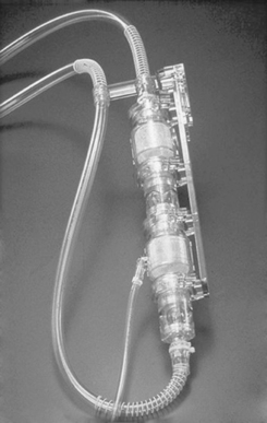 |
| FIGURE 23-1 Pneumatically driven Abiomed BVS Blood Pump. (Courtesy ABIOMED, Inc, Danvers, Mass.) |
 |
| FIGURE 23-2 Mechanically driven Thoratec HeartMate XVE LVAS. (Courtesy Thoratec Corporation, Pleasanton Calif.) |
Rotary blood pumps, contrary to the volume-displacement pumps, draw blood continuously from the supported heart. Rotary blood pumps do not have a blood collecting chamber or unidirectional valves and do not pause for optimal filling. They do have inflow and outflow cannulae, similar to the first-generation pumps, but instead of the blood chamber, they contain a high speed impeller. The impeller is likened to a turbine engine or propeller. Because rotary pumps draw blood continuously from the supported ventricle, pulsatility of the affected side may be dampened significantly. If the VAD is supporting the left side of the heart, for example, a peripheral pulse may be difficult to palpate, necessitating use of a Doppler flow probe to auscultate and confirm blood flow. Basic assessment skills of adequate circulation (e.g., capillary bed refill, adequate mentation, urine output, etc) have heightened importance in these patients.
Rotary blood pumps further differentiate into the second-generation and third-generation pumps. The rotary pump impeller uses rotational energy to propel the blood through the pump. It may be cylindrical or disc-shaped and uses blades or vanes to direct the blood flow forward. The second-generation rotary blood pumps are axial flow devices in which the blood path across the cylindrical impeller is linear, relying on circumferential energy (Figure 23-3). The rotational speed of an axial flow device is typically 8000 to 15,000 rpm. Examples of axial flow pumps available in the United States include the HeartMate II LVAS (Thoratec Corporation), the Jarvik 2000 (Jarvik Heart, Inc, New York), and the DeBakey LVAD (MicroMed Cardiovascular Inc, Houston).
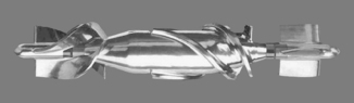 |
| FIGURE 23-3 Thoratec HeartMate II LVAS impeller. (Courtesy Thoratec Corporation, Pleasanton, Calif.) |
The third-generation rotary pumps are centrifugal flow devices in which the blood path through the disc impeller involves a 90-degree turn via the perpendicular inflow and outflow ports, combining both centrifugal and circumferential energy to propel the blood forward (Figure 23-4). The rotational speed of the centrifugal pump is typically 2000 to 4000 rpm. In addition, the centrifugal blood pump impeller is magnetically or hydrodynamically (because of the flow of blood through the pump) suspended, which eliminates the amount of contacting mechanical surfaces that otherwise wear with time. 2,16 Consequently, third-generation pumps are often referred to as “wearless” pumps. As the technology advances through these generations, fewer and fewer contacting moving parts are used. The devices, inherent to their design, have also become smaller and more energy efficient. The benefits of these advances are that the pumps will likely last longer and can be implanted in a wider range of body sizes, which makes the technology more accessible to more patients. Examples of temporary external centrifugal pumps currently available in the United States include the TandemHeart System (CardiacAssist Inc, Pittsburgh) and the CentriMag VAD (Thoratec Corporation). The implantable centrifugal pumps currently or imminently available in the United States include the VentrAssist LVAD (Ventracor, Inc, Budd Lake, NJ), the DuraHeart LVAS (Terumo Heart, Inc, Ann Arbor, Mich), and the HeartWare LVAS (HeartWare, Inc, Framingham, Mass).
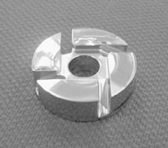 |
| FIGURE 23-4 HeartWare LVAS impeller. (Courtesy HeartWare, Inc, Framingham, Mass.) |
Of the six second-generation devices previously described, only the HeartMate II LVAS has FDA approval to date, specifically for bridge to transplant therapy only. The remaining axial and centrifugal pumps are in clinical trials in the United States for bridge to transplant, and destination therapy in some cases.
ACUTE CARDIOGENIC SHOCK DEVICES
As previously described, VADs used for acute cardiogenic shock are those devices indicated for immediate stabilization of the patient’s condition with an average projected support time of 7 to 10 days. Common indications for these devices include acute cardiogenic shock associated with myocardial infarction, postcardiotomy shock, viral myocarditis, and temporary right ventricular failure (RVF) associated with implantation of a permanent LVAD. The advantage of these short-term devices is that they allow the clinical team the opportunity to stabilize the patient’s condition for a more clear understanding of the clinical pathology and etiology of the cardiogenic shock and the most appropriate course for further therapy. Strategies at this time include the addition of pharmacologic therapies to maximize the potential for recovery and permanent removal of the VAD versus maximizing the pharmacologic therapy to determine whether weaning of the VAD is not feasible. In the latter case, the next strategies to consider are patient eligibility for cardiac transplant versus the need and appropriateness of lifetime VAD therapy. In extreme cases, withdrawal of pharmacologic and mechanical support may be warranted and requested by next of kin.
Typical acute cardiogenic shock devices that may necessitate medical transport are the intraaortic balloon pump (IABP), the extracorporeal membrane oxygenator (ECMO), the Abiomed BVS Blood Pump or AB5000 Ventricle (ABIOMED, Inc), the TandemHeart PTVA System (CardiacAssist Inc), the CentriMag VAD (Thoratec Corporation), and the Thoratec Paracorporeal or Implantable VADs (Thoratec Corporation). The major components of these blood pumps typically include cannulae that are attached to the appropriate anatomic part of the native circulation (i.e., blood vessels versus chambers of the heart) and then to the blood pump; the blood pump itself, which may either connect directly to the cannulae or require blood tubing to connect to the cannulae; and the console that runs the pump and provides power to the system, whether with electrical plug connections when stationary or with internal batteries for transportation of the patient while on support. All of these devices currently require systemic anticoagulation therapy to minimize the potential for thrombus formation and occlusion and also minimize the potential for excessive bleeding and its associated complications, including multiple blood transfusions and subsequent right heart failure. Heparin is used most commonly, although an alternative agent such as argatroban may be needed if the patient has positive test results for heparin-induced thrombocytopenia (HIT). More long-term support of the AB5000 Ventricle and the Thoratec Implantable Ventricular Assist Device (IVAD) and Paracorporeal Ventricular Assist Device (PVAD) does allow for conversion of heparin to warfarin.
Intraaortic Balloon Pump
An intraaortic balloon pump (IABP) is a device whose primary purpose is to increase blood flow to the heart muscle through the coronary arteries with the assistance of diastole and to decrease the heart’s workload through a process called counterpulsation. The secondary effects are the improvement of cardiac output (CO), stroke volume (SV), left ventricular emptying, and ejection fraction (EF). An increase in coronary perfusion pressure and systemic perfusion, with a decrease of heart rate, pulmonary capillary wedge pressure (PCWP), and systemic vascular resistance (SVR), also occurs. 11 This device is ideal for patients with poor cardiac output, chest pain unrelieved with medical therapy, and failed pharmacologic therapy associated with poor perfusion related to cardiogenic shock.
Placement of the IABP typically involves inserting a flexible catheter into the femoral artery and advancing it into the descending thoracic aorta (Figure 23-5). The placement of the catheter is confirmed with fluoroscopy or chest radiograph. As illustrated in Figure 23-5, proper location of the catheter is essential for ideal functioning. Poor placement of the IABP catheter can create other complications that are discussed subsequently in this section.
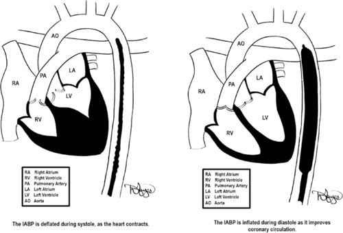 |
| FIGURE 23-5 Placement of IABP balloon-tipped catheter. The goal of inflation is to produce a rapid rise in aortic pressure optimizing diastolic augmentation, thereby increasing oxygen supply to the coronaries. During deflation, the reduction in end aortic diastolic pressure (afterload) causes improved cardiac performance. (Drawings courtesy of David Hayes.) |
The newer generation intraaortic balloon pump offers operator flexibility, which allows the flight crew members the capability to care for a broad range of patients. These pumps are designed to work in conditions unique to the operating room, to the cardiac catheterization laboratory, to the intensive care unit (ICU), and to air and surface transport. The technology uses speed and quick algorithms, supplying support to patients with arrhythmias. 3 The balloon pumps have colorful display panels combined with pneumatic and electronic innovations. These balloon pumps possess cardiosynchronization capabilities, with auto select trigger selection and timing. The IABP adapts its deflation automatically while supporting ventricular ectopy or other arrhythmias. 20 If the timing is not correct, a number of physiologic changes can occur, as outlined in Table 23-1.
| Timing Error | Effect |
|---|---|
| Early inflation | Premature closure of the aortic valve causing aortic regurgitation |
| Late inflation | Sub-optimal coronary perfusion |
| Early deflation | Retrograde coronary blood flow |
| Late deflation | Increases the resistance the balloon pumps against (afterload) |
The automatic mode of the IABP uses the ECG trigger, but if the ECG trigger is lost, the pump searches for the next best trigger source and resets the time accordingly. A manual mode allows the transport team members to select and control all of the triggers and their timing even during changes in rhythm. This technology allows the flight team members to focus more on the patient and aviation safety rather than the pump.
Because of the large amount of background noise in air medical transport, the IABP console supports a large visual alarm display. The balloon is filled with a predetermined amount of helium. With use of the manual mode in the previous generation of these pumps (DataScope 97 and 98XT [Datascope, Corp., Fairfield NJ]), the pumps needed manual autofilling of the balloon catheter to compensate for the changes in balloon volume during air transport. This was done by the transport teams for every 2000 ft on ascent and 1000 ft on descent. 3 The newest generation IABP automatically refills the helium based on volume sensors, which detect changes in the volume of helium, prompting auto refill. This refilling also occurs every 2 hours automatically in manual or auto modes. In situations of very rapid descent, the pump refills many times, quickly causing a helium loss alarm.
The frequency of IABP counterpulsation is ordered by the physician. In most cases, it is 1:1; thus, for each contraction of the native ventricles and opening of the aortic valve, the IABP catheter is triggered to inflate during the subsequent diastolic phase timed to the dicrotic notch (Figure 23-6). The counterpulsation can be set for other frequency modes, such as 1:2 and 1:3, for which inflation of the balloon occurs on the dicrotic notch on every second or third beat, respectively. The balloon then deflates again at the onset of native ventricular systole. The most common IABPs used during transport are the Datascope CS 100 and 300 (Datascope, Corp., Fairfield, NJ), and the Arrow AutoCAT and AutoCAT WAVE 2 (Arrow International, Reading, PA). These types of balloon pumps have made significant changes in the past decade. The pumps are more operator-friendly, and their computerized monitoring systems allow for automatic timing of the inflation and deflation of the balloon catheter. The pumps also have transport designs that are more lightweight and safety conscious for air surface transport personnel.
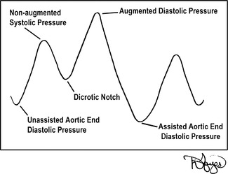 |
| FIGURE 23-6 IABP counterpulsation waveform. (Drawings courtesy of David Hayes.) |
Patient Assessment
A complete assessment of the patient’s hemodynamic status is vitally important before the transport of a patient with an IABP; however, the assessment should start with the primary survey. After the primary survey assessment and any interventions, a baseline neurologic examination is warranted. This examination is important because a highly placed IABP catheter can block blood flow to the subclavian and carotid artery.
The hemodynamic assessment should consist of evaluation of the patient’s CO, cardiac index (CI), left ventricular stroke work index (LVSWI), SVR, pulmonary vascular resistance (PVR), and other pulmonary catheter data, if available. Assessment of heart sounds should be done with the IABP on standby so that the sounds are clearly heard, with a baseline assessment provided for monitoring the possible accumulation of an excessive amount of fluid around the pericardium (cardiac tamponade). In air transport, hearing capabilities are impaired; therefore, all the important sound-assessed information should be obtained before leaving the referring facility. The assessment of the IABP includes diastolic augmentation, pump timing, and any alarms.
Although the use of pulmonary artery catheters has decreased significantly in the past several years, standard practice in critical care transport of these devices is the continuous monitoring of the pulmonary artery (PA) catheter waveforms. Hence, transport teams should be properly trained in the management of PA catheters and waveform analysis. If the catheter migrates into the PA, a wedge waveform is visualized on the monitor. This displacement can result in occlusion or perforation of the pulmonary artery, which can cause pulmonary infarct and possibly death. In this situation, the caregiver needs to ensure that the balloon is deflated and then pull the catheter back until the PA waveform is visualized on the monitor. In instances in which the PA catheter slips into the right ventricle, the catheter should be withdrawn.
Physical assessment of the patient to assure proper positioning is important because of the anatomic positioning of the IABP. The patient may have specific clinical assessment deficits. If the patient’s left brachial pulse is absent, the catheter may be positioned too high, causing occlusion of the subclavian artery and ultimately affecting blood flow to the left arm. A radiograph or fluoroscopy is best for identification of this misplacement. If the catheter is too low, the patient may have oliguria or anuria as a result of the catheter blocking the renal arteries, therefore decreasing renal blood flow.
Important laboratory values to review before transport include the most recent complete blood count (CBC), prothrombin time (PT), partial thromboplastin time (PTT), platelet counts, and basic metabolic panel. If oozing at the insertion site is present or occurs, use of a liter bag of intravenous (IV) fluids carefully placed over the exit site may be helpful. This placement applies light pressure without interfering with counterpulsation of the IABP. The oozing is most likely the result of the decrease in platelets caused by the counterpulsation of the IABP or anticoagulation effects from other medications. The head of the bed or stretcher (HOB) should be less than 30 degrees to prevent occlusion of the catheter. Light restraints or sedation may be helpful in securing the leg in which the catheter is inserted to prevent accidental IABP dislodgement or interference with balloon pump functioning. The diameter of the catheter varies from patient to patient; therefore, assessment for distal pulses is important to ensure perfusion of both extremities. An occlusion can cause ischemia of the affected extremity and result in clot formation, decreased circulation, and total arterial occlusion with possible amputation if the IABP is not adjusted or removed. The transport personnel must perform a thorough assessment and relay any complications from IABP therapy to the accepting physician with complete documentation in the flight chart.
Transport Considerations of the Patient with an Intraaortic Balloon Pump
1. In any vehicle, whether fixed or rotor-wing and ground, verify that the inverter can supply power to the IABP.
2. The two main manufactures of IABPs (Arrow and Datascope) both have adapters especially for transport personnel in the event the transport team’s pump is different from the one at the referring facility. These adapters allow interfacing between the two different pumps.
3. A transport bag should accompany all IABP transports with auxiliary supplies for IABPs.
4. Assure that sufficient helium and a backup helium tank are provided.
5. All blood pressure readings should be taken from the IABP console, and not the noninvasive blood pressure cuff (NIBP) or manually. The highest pressure sensed or heard is the diastolic augmentation, not systolic. Therefore, documentation of the NIBP or manual pressures provides inaccurate information.
6. Positioning the patient with the head toward the front of the fixed aircraft decreases the patient’s preload. The opposite occurs if the patient is positioned with the feet toward the front.
7. Ensure that the IABP console is plugged in whenever possible (e.g., in the transport vehicle and immediately on arrival at the bedside of the sending facility).
Management of Common Intraaortic Balloon Pump Emergency Procedures
In the transport environment, preparation for the worst case scenario in patient care and safety is a fact of life. Table 23-2 lists some emergencies that can occur with IABP therapy and their management.
| Problem | Intervention |
|---|---|
| Ventricular fibrillation (vfib) or pulseless ventricular tachycardia (VT) arrest | Follow Advanced Cardiac Life Support (ACLS) guidelines. Stopping the pump is not necessary. Pump is grounded and can accommodate electrical shocks. |
| Cardiopulmonary arrest: asystole or pulseless electrical activity (PEA) | Begin ACLS guidelines, and place pump on pressure mode during CPR. IABP pump will continue to pump with CPR as pressure is sensed. |
| Power failure | Attach 60-mL syringe to proximal stopcock and inflate IABP catheter once every 3-5 min to prevent clot formation on catheter. |
| Balloon rupture (evidenced by blood in the sheath, loss gas alarm, and rust-colored flecks) | Stop the pump immediately, clamp the catheter, and position patient in the left lateral position. |
Future Trends
As we have seen with IABP therapy in the past decade, balloon pumps have become smaller, smarter, and more user-friendly. Technologic advancement has switched focus from the pump console to the fiberoptic catheter. The fiber optic balloon pump catheter provides transport teams with two arterial waveform sources. 6 The traditional waveform is from the conventional transducer. The newer waveform is from the fiberoptic tip of the catheter inside the aorta. The traditional monitoring of arterial waveforms from transducers is delayed, whereas the fiberoptic waveform is in real time. 7 This real-time method provides more accurate timing. The transport considerations with these new catheters require the user to ensure it is properly zeroed and calibrated to the specifications of the manufacturer. At altitudes greater than 10,000 ft in an unpressurized cabin, the fiberoptic catheters may be altered and inoperable. They are more accurate below 10,000 ft. 3
Abiomed Circulatory Support Systems: BVS Blood Pump and AB5000 Ventricle
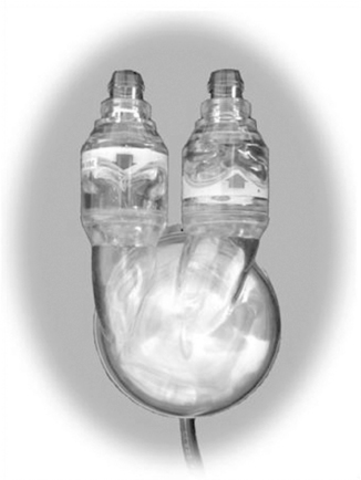
The Abiomed BVS Blood Pump is a first-generation volume-displacement VAD. It received initial FDA approval in 1994 and is capable of providing RVAD, LVAD, or BVAD support. The BVS Blood Pump is a columnar blood pump that contains two blood sacs, an atrial and a ventricular chamber (see Figure 23-1 on page 439). The device-specific artificial trileaflet valves are located between the two bladders and distal to the ventricular bladder. A pneumatic (air-filled) flexible cable is attached to the blood pump at the level of the ventricular bladder at one end and to the external console at the other end.
Compressed air trapped within the external console and pneumatic cable is then shunted between the console and the blood pump, which causes external pressure on the collapsible ventricular blood sac during the ejection phase of the pumping cycle, with subsequent release of that pressure during the filling phase. The pressure changes associated with filling and emptying of the ventricular bladder cause the proximal and distal valves to open and close, ensuring unidirectional flow of blood through the blood pump. Of note, the atrial bladder does not have a valve preceding it, so blood flows continuously into the atrial bladder, which is preload dependent. As with other volume-displacement first-generation pumps, the pump rate is dependent on the filling time of the ventricular chamber within a maximum period of time. Filling of the ventricular chamber is monitored by the console per the volume of displaced air through the pneumatic cable. Once the maximal amount of air is sensed by the console, the compressor shunts trapped air back, maintaining a minimum pump rate of 40 bpm.
To ensure adequate blood flow into the blood pump, the atrial bladder must be placed at a height relative to the patient’s right atrium (Figure 23-7). The blood pump can be placed too high relative to the patient so that blood flow into the pump is limited. Conversely, if placement is too low, blood pump output may be limited.
 |
| FIGURE 23-7 Positioning of the Abiomed BVS Blood Pump. (Courtesy ABIOMED, Inc, Danvers, Mass.) |
The BVS blood pump is connected to the patient’s circulation with device-specific cannulae. The inflow cannulae to the pump may be inserted into the native atria or ventricle, and the outflow cannulae are connected to the major artery attached to the side of the heart being supported. For RVAD support, typically the right atrium (RA) and pulmonary artery (PA) are the inflow and outflow cannulation sites, respectfully. For LVAD support, the left atrium (LA) or left ventricle (LV) may be used for the inflow cannula, and the aorta (Ao), typically the ascending portion, is used for outflow cannulation (Figure 23-8).
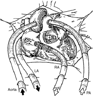 |
| FIGURE 23-8 Cannulation options for the Abiomed CSS. (Courtesy ABIOMED, Inc, Danvers, Mass.) |
The Abiomed AB5000 Ventricle (ABV) received FDA approval through a postmarket approval (PMA) supplement in September 2003, with the longest support of a patient to date being greater than 300 days. The device consists of a single blood sac made of a special polyurethane material that is encased in a hard clear outer shell (Figure 23-9). Between the blood sac and outer case is a lubricant to protect blood sac integrity. Device-specific artificial valves are located in the inflow and outflow connectors (conduits) of the pump to ensure unidirectional blood flow through the pump. The pump casing has a similar flexible pneumatic cable that connects the blood pump to the external console.
 |
| FIGURE 23-9 Abiomed AB5000 Ventricle. (Courtesy ABIOMED, Inc, Danvers, Mass.) |
Similarly, compressed air trapped within the external console and pneumatic cable is then shunted between the console and the blood pump, which causes external pressure on the blood sac during the ejection phase of the pumping cycle and release of that pressure during the filling phase. Unlike the BVS Blood Pump, the console does actively apply vacuum pressure to the AB5000 Ventricle to assist in filling the blood sac. The pressure changes associated with filling and emptying of the blood sac cause the proximal and distal valves to open and close to ensure unidirectional blood flow. The cannulae for attachment of the pump to the native circulation are the same as for the BVS Blood Pump, with similar cannulation sites as well. Both the BVS Blood Pump and the AB5000 Ventricle require open heart surgery for implantation.
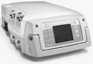
ABIOMED has recently streamlined the technology so that the same external console, the AB5000 Console, may be used for both pumps, with one console for RVAD and LVAD support simultaneously if indicated (Figure 23-10). The distal ends of the pneumatic cables for the BVS Blood Pump and AB5000 Ventricle differ so that their connection to the console indicates to the console which device it is supporting. This differentiation is important because the amount of external pressure applied to the AB5000 Ventricle for adequate ejection is typically much higher than the BVS Blood Pump and more for an LVAD than an RVAD within each device type. In addition, a more measurable vacuum effect is used during filling of the AB5000 Ventricle than with the BVS Blood Pump. The console allows for manual adjustment of the amount of vacuum for the AB5000 Ventricle and for adjustment of alarm triggers for both devices. VAD flows for both devices range from 3 to 6 L per minute (lpm), with beat rates ranging from 40 to 60 bpm with normal automatic console function. The display screen provides information regarding pump beat rate, pump flow, alarm settings, vacuum pressure for the AB5000 Ventricle specifically, and alarm events with troubleshooting instructions. The console may also be programmed to a weaning mode that allows limitation of VAD support in an attempt to wean the native heart from the device. Should the VAD fail completely, a hand pump is attached to the console to support manual pumping of either device, whether univentricular or biventricular assist. The hand pump is directed with specific toggle buttons that must be manually preset to indicate which side of the heart is being supported and with which device (BVS versus ABV).
 |
| FIGURE 23-10 Abiomed AB5000 console. (Courtesy ABIOMED, Inc, Danvers, Mass.) |
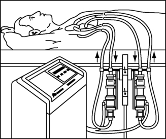
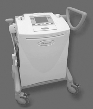
A discerning feature of the ABV from the BVS blood pump is that the ABV is capable of providing more long-term support with fewer bleeding and clotting issues. Unfortunately, the AB5000 Console is a hospital-based console with limited battery support of up to 1 hour. ABIOMED is in the midst of a clinical trial to evaluate the use of a portable driver for out-of-hospital support (Figure 23-11). Pending the results of this trial, in the future, patients who need prolonged Abiomed CSS support may be discharged into the community with the portable driver, allowing them improved quality of life while awaiting explantation of the device.
 |
| FIGURE 23-11 Abiomed portable console. (Courtesy ABIOMED, Inc, Danvers, Mass.) |
Frequent assessment of these pumps includes monitoring for adequate filling and emptying of the blood chambers and the presence of thrombus or fibrin layering. The most likely locations for fibrin or thrombus formation in the pumps are areas of low flow, specifically at the bases of the artificial valves, although they may also be identified on the surfaces of the bladders or blood sacs, or at the connections of the blood tubing. Initially, both blood pumps require full anticoagulation therapy with heparin, or argatroban if the patient is considered HIT positive. Anticoagulation goals may be altered if patient is coagulopathic or actively bleeding or if the device flow drops below 3 lpm. If prolonged support is necessary, which is most likely with the ABV, the intravenous anticoagulation therapy may be converted over to warfarin.
< div class='tao-gold-member'>
Only gold members can continue reading. Log In or Register to continue
Related posts:


Full access? Get Clinical Tree
