Key Points
Related Matter
Grounded Electrical Power
Electric Plugs
Line Isolation
Line Isolation Monitor
Return Plate
Fire in the Operating Room
The myriad of electrical and electronic devices in the modern operating room (OR) greatly improve patient care and safety. However, these devices also subject both the patient and OR personnel to increased risks. To reduce the risk of electrical shock, most ORs have electrical systems that incorporate special safety features. It is incumbent upon the anesthesiologist to have a thorough understanding of the basic principles of electricity and an appreciation of the concepts of electrical safety applicable to the OR environment.
Principles of Electricity
where E is electromotive force (in volts), I is current (in amperes), and R is resistance (in ohms). Ohm’s law forms the basis for the physiologic equation BP = CO × SVR; that is, blood pressure (BP) is equal to the cardiac output (CO) times the systemic vascular resistance (SVR). In this case, the blood pressure of the vascular system is analogous to voltage, the cardiac output to current, and the systemic vascular resistance to the forces opposing the flow of electrons. Electrical power (P) is measured in watts (W). Power is the product of the voltage (E) and the current (I), as defined by the formula:
The amount of electrical work done is measured in watts multiplied by a unit of time. The watt-second (a joule, J) is a common designation for electrical energy expended in doing work. The energy produced by a defibrillator is measured in watt-seconds (or joules). The kilowatt-hour is used by electrical utility companies to measure larger quantities of electrical energy.
Power can be thought of as a measure not only of work done but also of heat produced in any electrical circuit. Substituting Ohm’s law in the formula:

Thus, power is equal to the square of the current I2 (amperage) times the resistance R. Using these formulas, it is possible to calculate the number of amperes and the resistance of a given device if the wattage and the voltage are known. For example, a 60-watt light bulb operating on a household 120-volt circuit would require 0.5 ampere of current for operation. Rearranging the formula so that:
We have:
Using this in Ohm’s law:
The resistance can be calculated to be 240 ohms:
It is obvious from the previous discussion that 1 volt of electromotive force (EMF) flowing through a 1-ohm resistance will generate 1 ampere of current. Similarly, 1 ampere of current induced by 1 volt of EMF will generate 1 watt of power.
Direct and Alternating Currents
Any substance that permits the flow of electrons is called a conductor. Current is characterized by electrons flowing through a conductor. If the electron flow is always in the same direction, it is referred to as direct current (DC). However, if the electron flow reverses direction at a regular interval, it is termed alternating current (AC). Either of these types of current can be pulsed or continuous in nature.
The previous discussion of Ohm’s law is accurate when applied to DC circuits. However, when dealing with AC circuits, the situation is more complex because the flow of the current is opposed by a more complicated form of resistance, known as impedance.
Impedance
Impedance, designated by the letter Z, is defined as the sum of the forces that oppose electron movement in an AC circuit. Impedance consists of resistance (ohms) but also takes capacitance and inductance into account. In actuality, when referring to AC circuits, Ohm’s law is defined as:
An insulator is a substance that opposes the flow of electrons. Therefore, an insulator has a high impedance to electron flow, whereas a conductor has a low impedance to electron flow.
In AC circuits, the capacitance and inductance can be important factors in determining the total impedance. Both capacitance and inductance are influenced by the frequency (cycles per second or hertz, Hz) at which the AC current reverses direction. The impedance is directly proportional to the frequency (f) times the inductance (IND):
and the impedance is inversely proportional to the product of the frequency (f) and the capacitance (CAP):
As the AC current increases in frequency, the net effect of both capacitance and inductance increases. However, because impedance and capacitance are inversely related, total impedance decreases as the product of the frequency and the capacitance increases. Thus, as frequency increases, impedance falls and more current is allowed to pass.
Capacitance
A capacitor consists of any two parallel conductors that are separated by an insulator (Fig. 8-1). A capacitor has the ability to store charge. Capacitance is the measure of that substance’s ability to store charge. In a DC circuit the capacitor plates are charged by a voltage source (i.e., a battery) and there is only a momentary current flow. The circuit is not completed and no further current can flow unless a resistance is connected between the two plates and the capacitor is discharged.
In contrast to DC circuits, a capacitor in an AC circuit permits current flow even when the circuit is not completed by a resistance. This is because of the nature of AC circuits, in which the current flow is constantly being reversed. Because current flow
results from the movement of electrons, the capacitor plates are alternately charged—first positive and then negative with every reversal of the AC current direction—resulting in an effective current flow as far as the remainder of the circuit is concerned, even though the circuit is not completed.
results from the movement of electrons, the capacitor plates are alternately charged—first positive and then negative with every reversal of the AC current direction—resulting in an effective current flow as far as the remainder of the circuit is concerned, even though the circuit is not completed.
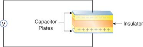 Figure 8.1. A capacitor consists of two parallel conductors separated by an insulator. The capacitor is capable of storing charge supplied by a voltage source. |
Since the effect of capacitance on impedance varies directly with the AC frequency in hertz, the greater the AC frequency, the lower the impedance. Therefore, high-frequency currents (0.5 to 2 million Hz), such as those used by electrosurgical units (ESUs), will cause a marked decrease in impedance.
Electrical devices use capacitors for various beneficial purposes. There is, however, a phenomenon known as stray capacitance—capacitance that was not designed into the system but is incidental to the construction of the equipment. All AC-operated equipment produces stray capacitance. An ordinary power cord, for example, consisting of two insulated wires running next to each other will generate significant capacitance simply by being plugged into a 120-volt circuit, even though the piece of equipment is not turned on. Another example of stray capacitance is found in electric motors. The circuit wiring in electric motors generates stray capacitance to the metal housing of the motor. The clinical importance of capacitance will be emphasized later in the chapter.
Inductance
Whenever electrons flow in a wire, a magnetic field is induced around the wire. If the wire is coiled repeatedly around an iron core, as in a transformer, the magnetic field can be very strong. Inductance is a property of AC circuits in which an opposing EMF can be electromagnetically generated in the circuit. The net effect of inductance is to increase impedance. Since the effect of inductance on impedance also depends on AC frequency, increases in frequency will increase the total impedance. Therefore, the total impedance of a coil will be much greater than its simple resistance.
Electrical Shock Hazards
Alternating and Direct Currents
Whenever an individual contacts an external source of electricity, an electrical shock is possible. An electrical current can stimulate skeletal muscle cells to contract, and thus can be used therapeutically in devices such as pacemakers or defibrillators. However, casual contact with an electrical current, whether AC or DC, can lead to injury or death. Although it takes approximately 3 times as much DC as AC to cause ventricular fibrillation, this by no means renders DC harmless. Devices such as an automobile battery or a DC defibrillator can be sources of DC shocks.
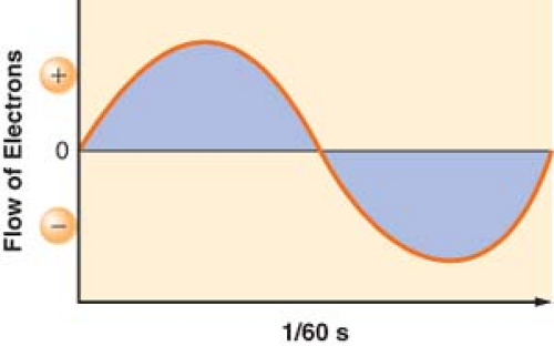 Figure 8.2. Sine wave flow of electrons in a 60 Hz AC. |
In the United States, utility companies supply electrical energy in the form of ACs of 120 volts at a frequency of 60 Hz. The 120 volts of EMF and 1 ampere of current are the effective voltage and amperage in an AC circuit. This is also referred to as RMS (root-mean-square). It takes 1.414 amperes of peak amperage in the sinusoidal curve to give an effective amperage of 1 ampere. Similarly, it takes 170 volts (120 × 1.414) at the peak of the AC curve to get an effective voltage of 120 volts. The 60 Hz refers to the number of times in 1 second that the current reverses its direction of flow. Both the voltage and current waveforms form a sinusoidal pattern (Fig. 8-2).
The power company attempts to maintain the line voltage constant at 120 volts. Therefore, by Ohm’s law, the current flow is inversely proportional to the impedance. A typical power cord consists of two conductors. One, designated as hot carries the current to the impedance; the other is neutral, and it returns the current to the source. The potential difference between the two is effectively 120 volts (Fig. 8-3). The amount of current flowing through a given device is frequently referred to as the load. The load of the circuit depends on the impedance. A very high impedance circuit allows only a small current to flow and thus has a small load. A very low impedance circuit will draw a large
current and is said to be a large load. A short circuit occurs when there is a zero impedance load with a very high current flow.1
current and is said to be a large load. A short circuit occurs when there is a zero impedance load with a very high current flow.1
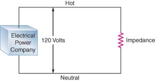 Figure 8.3. A typical AC circuit where there is a potential difference of 120 volts between the hot and neutral sides of the circuit. The current flows through a resistance, which in AC circuits is more accurately referred to as impedance, and then returns to the electrical power company. |
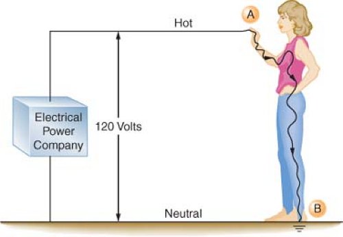 Figure 8.4. An individual can complete an electric circuit and receive a shock by coming in contact with the hot side of the circuit (point A). This is because he or she is standing on the ground (point B) and the contact point A and the ground point B provide the two contact points necessary for a completed circuit. The severity of the shock that the individual receives depends on his or her skin resistance. |
Source of Shocks
When an individual contacts a source of electricity, damage occurs in one of two ways. First, the electrical current can disrupt the normal electrical function of cells. Depending on its magnitude, the current can contract muscles, alter brain function, paralyze respiration, or disrupt normal heart function, leading to ventricular fibrillation. The second mechanism involves the dissipation of electrical energy throughout the body’s tissues. An electrical current passing through any resistance raises the temperature of that substance. If enough thermal energy is released, the temperature will rise sufficiently to produce a burn. Accidents involving household currents usually do not result in severe burns. However, in accidents involving very high voltages (i.e., power transmission lines), severe burns are common.
The severity of an electrical shock is determined by the amount of current (number of amperes) and the duration of the current flow. For the purpose of this discussion, electrical shocks are divided into two categories. Macroshock refers to large amounts of current flowing through a person, which can cause harm or death. Microshock refers to very small amounts of current and applies only to the electrically susceptible patient. This is an individual who has an external conduit that is in direct contact with the heart. This can be a pacing wire or a saline-filled catheter such as a central venous or pulmonary artery catheter. In the case of the electrically susceptible patient, even minute amounts of current (microshock) may cause ventricular fibrillation.
Table 8-1 shows the effects typically produced by various currents following a 1-second contact with a 60 Hz current. When an individual contacts a 120-volt household current, the severity of the shock will depend on his or her skin resistance, the duration of the contact, and the current density. Skin resistance can vary from a few thousand to 1 million ohms. If a person with a skin resistance of 1,000 ohms contacts a 120-volt circuit, he or she would receive 120 milliamperes (mA) of current, which would probably be lethal. However, if that same person’s skin resistance is 100,000 ohms, the current flow would be 1.2 mA, which would barely be perceptible.
Table 8-1. Effects of 60-hz Current on an Average Human for A 1-Second Contact | ||||||||||||||||||||||||
|---|---|---|---|---|---|---|---|---|---|---|---|---|---|---|---|---|---|---|---|---|---|---|---|---|
| ||||||||||||||||||||||||
The longer an individual is in contact with the electrical source, the more dire the consequences, because more energy will be released and more tissue damaged. Also, there will be a greater chance of ventricular fibrillation from excitation of the heart during the vulnerable period of the electrocardiogram (ECG) cycle.
Current density is a way of expressing the amount of current that is applied per unit area of tissue. The diffusion of current in the body tends to be in all directions. The greater the current or the smaller the area to which it is applied, the higher the current density. In relation to the heart, a current of 100 mA (100,000 μA) is generally required to produce ventricular fibrillation when applied to the surface of the body. However, only 100 μA (0.1 mA) is required to produce ventricular fibrillation when that minute current is applied directly to the myocardium through an instrument having a very small contact area, such as a pacing wire electrode. In this case, the current density is 1,000-fold greater when applied directly to the heart; therefore, only 1/1,000 of the energy is required to cause ventricular fibrillation. In this case, the electrically susceptible patient can be electrocuted with currents well below 1 mA, which is the threshold of perception for humans. The frequency at which the current reverses is also an important
factor in determining the amount of current an individual can safely contact. Utility companies in the United States produce electricity at a frequency of 60 Hz. They use 60 Hz because higher frequencies cause greater power loss through transmission lines and lower frequencies cause a detectable flicker from light sources.2 The “let-go” current is defined as that current above which sustained muscular contraction occurs and at which an individual would be unable to let go of an energized wire. The let-go current for a 60 Hz AC power is 10 to 20 mA,1,3,4 whereas at a frequency of 1 million Hz, up to 3 amperes (3,000 mA) is generally considered safe. It should be noted that very high frequency currents do not excite contractile tissue; consequently, they do not cause cardiac dysrhythmias.
factor in determining the amount of current an individual can safely contact. Utility companies in the United States produce electricity at a frequency of 60 Hz. They use 60 Hz because higher frequencies cause greater power loss through transmission lines and lower frequencies cause a detectable flicker from light sources.2 The “let-go” current is defined as that current above which sustained muscular contraction occurs and at which an individual would be unable to let go of an energized wire. The let-go current for a 60 Hz AC power is 10 to 20 mA,1,3,4 whereas at a frequency of 1 million Hz, up to 3 amperes (3,000 mA) is generally considered safe. It should be noted that very high frequency currents do not excite contractile tissue; consequently, they do not cause cardiac dysrhythmias.
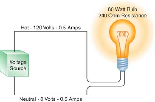 Figure 8.5. A 60-watt light bulb has an internal resistance of 240 ohms and draws 0.5 ampere of current. The voltage drop in the circuit is from 120 in the hot wire to 0 in the neutral wire, but the current is 0.5 ampere in both the hot and neutral wires. |
It can be seen that Ohm’s law governs the flow of electricity. For a completed circuit to exist, there must be a closed loop with a driving pressure to force a current through a resistance, just as in the cardiovascular system there must be a blood pressure to drive the cardiac output through the peripheral resistance. Figure 8-5 illustrates that a hot wire carrying a 120-volt pressure through the resistance of a 60-watt light bulb produces a current flow of 0.5 ampere. The voltage in the neutral wire is approximately 0 volts, while the current in the neutral wire remains at 0.5 ampere. This correlates with our cardiovascular analogy, where a mean blood pressure decrease of 80 mm Hg between the aortic root and the right atrium forces a cardiac output of 6 L/min through a systemic vascular resistance of 13.3 resistance units. However, the flow (in this case, the cardiac output, or in the case of the electrical model, the current) is still the same everywhere in the circuit. That is, the cardiac output on the arterial side is the same as the cardiac output on the venous side.
Grounding
Table 8-2. Differences Between Power and Equipment Grounding in the Home and the Operating Room | ||||||||||||
|---|---|---|---|---|---|---|---|---|---|---|---|---|
| ||||||||||||
Electrical Power: Grounded
Electrical utilities universally provide power that is grounded (by convention, the earth-ground potential is zero, and all voltages represent a difference between potentials). That is, one of the wires supplying the power to a home is intentionally connected to the earth. The utility companies do this as a safety measure to prevent electrical charges from building up in their wiring during electrical storms. This also prevents the very high voltages used in transmitting power by the utility from entering the home in the event of an equipment failure in their high-voltage system.
The power enters the typical home via two wires. These two wires are attached to the main fuse or the circuit breaker box at the service entrance. The “hot” wire supplies power to the “hot” distribution strip. The neutral wire is connected to the neutral distribution strip and to a service entrance ground (i.e., a pipe buried in the earth; Fig. 8-6). From the fuse box, three wires leave to supply the electrical outlets in the house. In the United States, the hot wire is color-coded black and carries a voltage 120 volts above ground potential. The second wire is the neutral wire color-coded white; the third wire is the ground wire, which is either color-coded green or is uninsulated (bare wire). The ground and the neutral wires are attached at the same point in the circuit breaker box and then further connected to a cold-water pipe (Figs. 8-7 and 8-8). Thus, this grounded power system is also referred to as a neutral grounded power system. The black wire is not connected to the ground, as this would create a short circuit. The black wire is attached to the hot (i.e., 120 volts above ground) distribution strip on which the circuit breakers or fuses are located. From here, numerous branch circuits supply electrical power to the outlets in the house. Each branch circuit is protected by a circuit breaker or fuse that limits current to a specific maximum amperage. Most electrical circuits in the house are 15- or 20-ampere circuits. These typically supply power to the electrical outlets and lights in the house. Several higher amperage circuits are also provided for devices such as an electric stove or an electric clothes dryer. These devices are powered by 240-volt circuits, which can draw from 30 to 50 amperes of current. The circuit breaker or fuse will interrupt
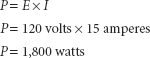
the flow of current on the hot side of the line in the event of a short circuit or if the demand placed on that circuit is too high. For example, a 15-ampere branch circuit will be capable of supporting 1,800 watts of power.
the flow of current on the hot side of the line in the event of a short circuit or if the demand placed on that circuit is too high. For example, a 15-ampere branch circuit will be capable of supporting 1,800 watts of power.
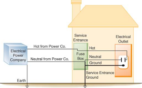 Figure 8.6. In a neutral grounded power system, the electric company supplies two lines to the typical home. The neutral wire is connected to ground by the power company and again connected to a service entrance ground when it enters the fuse box. Both the neutral and ground wires are connected together in the fuse box at the neutral bus bar, which is also attached to the service entrance ground. |
Therefore, if two 1,500-watt hair dryers were simultaneously plugged into one outlet, the load would be too great for a 15-ampere circuit, and the circuit breaker would open (trip) or the fuse would melt. This is done to prevent the supply wires in the circuit from melting and starting a fire. The amperage of the circuit breaker on the branch circuit is determined by the thickness of the wire that it supplies. If a 20-ampere breaker is used with wire rated for only 15 amperes, the wire could melt and start a fire before the circuit breaker would trip. It is important to note that a 15-ampere circuit breaker does not protect an individual from lethal shocks. The 15 amperes of current that would trip the circuit breaker far exceeds the 100 to 200 mA that will produce ventricular fibrillation.
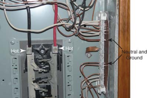 Figure 8.7. Inside a fuse box with the circuit breakers removed. The arrowheads indicate the hot wires energizing the strips where the circuit breakers are located. The arrows point to the neutral bus bar where the neutral and ground wires are connected. |
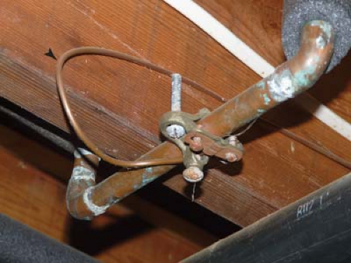 Figure 8.8. The arrowhead indicates the ground wire from the circuit breaker box attached to a cold-water pipe. |
The wires that leave the circuit breaker supply the electrical outlets and lighting for the rest of the house. In older homes, the electrical cable consists of two wires, a hot and a neutral, which supply power to the electrical outlets (Fig. 8-9). In newer homes, a third wire has been added to the electrical cable (Fig. 8-10). This third wire is either green or uninsulated (bare) and serves as a ground wire for the power receptacle (Fig. 8-11). On one end, the ground wire is attached to the electrical outlet (Fig. 8-12); on the other, it is connected to the neutral distribution strip in the circuit breaker box along with the neutral (white) wires (Fig. 8-13).
and between the hot wire and ground. In this case, the ground is the earth (Fig. 8-14). In modern home construction, there is still a 120-volt potential difference between the hot (black) and the neutral (white) wire as well as a 120-volt difference between the equipment ground wire (which is the third wire), and between the hot wire and earth (Fig. 8-15).
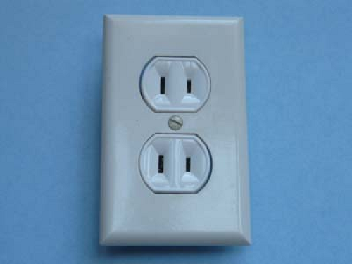 Figure 8.9. An older style electrical outlet consisting of just two wires (a hot and a neutral). There is no ground wire. |
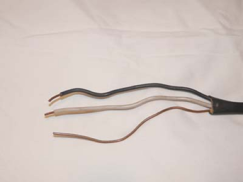 Figure 8.10. Modern electrical cable in which a third, or ground wire has been added. |
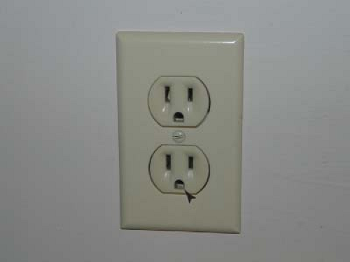 Figure 8.11. Modern electrical outlet in which the ground wire is present. The arrowhead points to the part of the receptacle where the ground wire connects. |
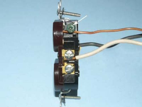 Figure 8.12. Detail of modern electrical power receptacle. The arrow points to the ground wire (bare wire), which is attached to the green grounding screw on the power receptacle. |
A 60-watt light bulb can be used as an example to further illustrate this point. Normally, the hot and neutral wires are connected to the two wires of the light bulb socket, and throwing the switch will illuminate the bulb (Fig. 8-16). Similarly, if the hot wire is connected to one side of the bulb socket and the other wire from the light bulb is connected to the equipment ground wire, the bulb will still illuminate. If there is no equipment ground wire, the bulb will still light if the second wire is connected to any grounded metallic object such as a water pipe or a faucet. This illustrates the fact that the 120-volt potential difference exists not only between the hot and the neutral wires but also between the hot wire and any grounded object. Thus, in a grounded power system, the current will flow between the hot wire and any conductor with an earth ground.
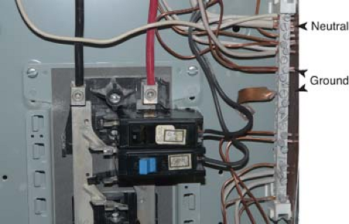 Figure 8.13. The ground wires (bare wires) from the power outlet are run to the neutral bus bar, where they are connected with the neutral wires (white wires) (arrowheads). |
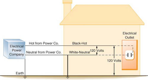 Figure 8.14. Diagram of a house with older style wiring that does not contain a ground wire. A 120-volt potential difference exists between the hot and the neutral wires, as well as between the hot wire and the earth. |
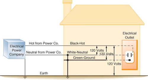 Figure 8.15. Diagram of a house with modern wiring in which the third, or ground, wire has been added. The 120-volt potential difference exists between the hot and neutral wires, the hot and the ground wires, and the hot wire and the earth. |
As previously stated, current flow requires a closed loop with a source of voltage. For an individual to receive an electric shock, he or she must contact the loop at two points. Because we may be standing on the ground or be in contact with an object that is referenced to ground, only one additional contact point is necessary to complete the circuit and thus receive an electrical shock. This is an unfortunate and inherently dangerous consequence of grounded power systems. Modern wiring systems have added the third wire, the equipment ground wire, as a safety measure to reduce the severity of a potential electrical shock. This is accomplished by providing an alternate, low-resistance pathway through which the current can flow to ground.
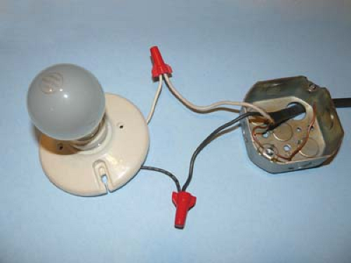 Figure 8.16. A simple light bulb circuit in which the hot (black) and neutral (white) wires are connected with the corresponding wires from the light bulb fixture. |
example, except that now the equipment ground wire is part of the electrical distribution system. In this example, the equipment ground wire provides a pathway of low impedance through which the current can travel; therefore, most of the current would travel through the ground wire. In this case, the person may get a shock, but it is unlikely to be fatal.
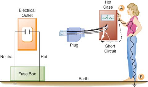 Figure 8.17. When a faulty piece of equipment without an equipment ground wire is plugged into an electrical outlet not containing a ground wire, the case of the instrument will become hot. An individual touching the hot case (point A) will receive a shock because he or she is standing on the earth (point B) and completes the circuit. The current (dashed line) will flow from the instrument through the individual touching the hot case. |
The electrical power supplied to homes is always grounded. A 120-volt potential always exists between the hot conductor and the ground or earth. The third or equipment ground wire used in modern electrical wiring systems does not normally have current flowing through it. In the event of a short circuit, an electrical device with a three-prong plug (i.e., a ground wire connected to its case) will conduct the majority of the short-circuited or “fault” current through the ground wire and away from the individual. This provides a significant safety benefit to someone accidentally contacting the defective device. If a large enough fault current exists, the ground wire also will provide a means to complete the short circuit back to the circuit breaker or fuse, and this will either melt the fuse or trip the circuit breaker. Thus, in a grounded power system, it is possible to have either grounded or ungrounded equipment, depending on when the wiring was installed and whether the electrical device is equipped with a three-prong plug containing a ground wire. Obviously, attempts to bypass the safety system of the equipment ground should be avoided. Devices such as a “cheater plug” (Fig. 8-19) should never be used because they defeat the safety feature of the equipment ground wire.
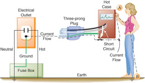 Figure 8.18. When a faulty piece of equipment containing an equipment ground wire is properly connected to an electrical outlet with a grounding connection, the current (dashed line) will preferentially flow down the low-resistance ground wire. An individual touching the case (point A) while standing on the ground (point B) will still complete the circuit; however, only a small part of the current will go through the individual. |
Electrical Power: Ungrounded
referred to as line 1 and line 2 (Fig. 8-22). Using the example of the light bulb, if one connects the two wires of the bulb socket to the two wires of the IPS, the light will illuminate. However, if one connects one of the wires to one side of the isolated power and the other wire to the ground, the light will not illuminate. If the wires of the IPS are connected, the short circuit will trip the circuit breaker. In comparing the two systems, the standard grounded power has a direct connection to ground, whereas the isolated system imposes a very high impedance to any current flow to ground. The added safety of this system can be seen in Figure 8-23. In this case, a person has come in contact with one side of the IPS (point A). Since standing on the ground (point B) does not constitute a part of the isolated circuit, the individual does not complete the loop and will not receive a shock. This is because the ground is part of the primary circuit (solid lines), and the person is contacting only one side of the isolated secondary circuit (cross-hatched lines). The person does not complete either circuit (i.e., have two contact points); therefore, this situation does not pose an electric shock hazard. Of course, if the person contacts both lines of the IPS (an unlikely event), he or she would receive a shock.
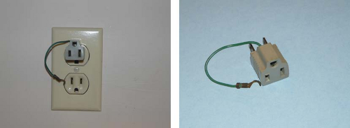 Figure 8.19. Right: A “cheater plug” that converts a three-prong power cord to a two-prong cord. Left: The wire attached to the cheater plug is rarely connected to the screw in the middle of the outlet. This totally defeats the purpose of the equipment ground wire. |
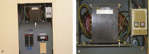 Figure 8.20. A: Isolated power panel showing circuit breakers, LIM, and isolation transformer (arrow). B: Detail of an isolation transformer with the attached warning lights. The arrow points to ground wire connection on the primary side of the transformer. Note that no similar connection exists on the secondary side of the transformer. |
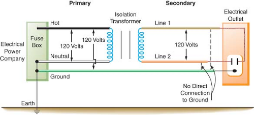 Figure 8.21. In the OR, the isolation transformer converts the grounded power on the primary side to an ungrounded power system on the secondary side of the transformer. A 120-volt potential difference exists between line 1 and line 2. There is no direct connection from the power on the secondary side to ground. The equipment ground wire, however, is still present. |
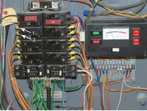 Figure 8.22. Detail of the inside of a circuit breaker box in an isolated power system. The bottom arrow points to ground (green) wires meeting at the common ground terminal. Arrows 1 and 2 indicate lines 1 and 2 (orange and brown) from the isolated power circuit breaker. Neither line 1 nor line 2 is connected to the same terminals as the ground wires. This is in marked contrast to Figure 8-13, where the neutral and ground wires are attached at the same point. |
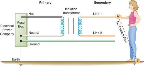 Figure 8.23. A safety feature of the isolated power system is illustrated. An individual contacting one side of the isolated power system (point A) and standing on the ground (point B) will not receive a shock. In this instance, the individual is not contacting the circuit at two points and thus is not completing the circuit. Point A is part of the isolated power system, and point B is part of the primary or grounded side of the circuit. |
If a faulty electrical appliance with an intact equipment ground wire is plugged into a standard household outlet, and the home wiring has a properly connected ground wire, then the amount of electrical current that will flow through the individual is considerably less than what will flow through the low-resistance ground wire. Here, an individual would be fairly well protected from a serious shock. However, if that ground wire were broken, the individual might receive a lethal shock. No shock would occur if the same faulty piece of equipment were plugged into the IPS, even if the equipment ground wire were broken. Thus, the IPS provides a significant amount of protection from macroshock. Another feature of the IPS is that the faulty piece of equipment, even though it may be partially short-circuited, will not usually trip the circuit breaker. This is an important feature because the faulty piece of equipment may be part of a life-support system for a patient. It is important to note that even though the power is isolated from ground, the case or frame of all electrical equipment is still connected to an equipment ground. The third wire (equipment ground wire) is necessary for a total electrical safety program.
Figure 8-24 illustrates a scenario involving a faulty piece of equipment connected to the IPS. This does not represent a hazard; it merely converts the isolated power back to a grounded power system as exists outside the OR. In fact, a second fault is necessary to create a hazard.
The previous discussion assumes that the IPS is perfectly isolated from ground. Actually, perfect isolation is impossible to achieve. All AC-operated power systems and electrical devices manifest some degree of capacitance. As previously discussed, electrical power cords, wires, and electrical motors exhibit capacitive coupling to the ground wire and metal conduits and “leak” small amounts of current to the ground (Fig. 8-25). This so-called leakage current partially ungrounds the IPS. This does not usually amount to more than a few milliamperes in an OR. So an individual coming in contact with one side of the IPS would receive only a very small shock (1 to 2 mA). Although this amount of current would be perceptible, it would not be dangerous.
The Line Isolation Monitor
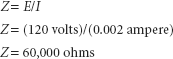
a conventional grounded system. Also, the faulty piece of equipment will continue to function normally. Therefore, it is essential that a warning system be in place to alert the personnel that the power is no longer ungrounded. The LIM continuously monitors the isolated power to ensure that it is indeed isolated from ground, and the device has a meter that displays a continuous indication of the integrity of the system (Fig. 8-26). The LIM is actually measuring the impedance to the ground of each side of the IPS. As previously discussed, with perfect isolation, impedance would be infinitely high and there would be no current flow in the event of a first fault situation (Z = E/I; if I = 0, then Z = ∞). Because all AC wiring and all AC-operated electrical devices have some capacitance, small leakage currents are present that partially degrade the isolation of the system. The meter of the LIM will indicate (in milliamperes) the total amount of leakage in the system resulting from capacitance, electrical wiring, and any devices plugged into the IPS.
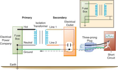 Figure 8.24. A faulty piece of equipment plugged into the isolated power system does not present a shock hazard. It merely converts the isolated power system into a grounded power system. The figure inset illustrates that the isolated power system is now identical to the grounded power system. The dashed line indicates current flow in the ground wire. |
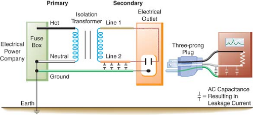 Figure 8.25. The capacitance that exists in alternating current (AC) power lines and AC-operated equipment results in small “leakage currents” that partially degrade the isolated power system. |
For example, if the LIM were set to alarm at 2 mA, using Ohm’s law, the impedance for either side of the IPS would be 60,000 ohms:
Therefore, if either side of the IPS had less than 60,000 ohms impedance to the ground, the LIM would trigger an alarm. This might occur in two situations. In the first situation, a faulty piece of equipment is plugged into the IPS. In this case, a true fault to ground exists from one line to ground. Now the system would be converted to the equivalent of a grounded power system. This faulty piece of equipment should be removed and serviced as soon as possible. However, this piece of equipment could still be used safely if it were essential for the care of the patient. It should
be remembered, however, that continuing to use this faulty piece of equipment would create the potential for a serious electrical shock. This would occur if a second faulty piece of equipment were simultaneously connected to the IPS.
be remembered, however, that continuing to use this faulty piece of equipment would create the potential for a serious electrical shock. This would occur if a second faulty piece of equipment were simultaneously connected to the IPS.
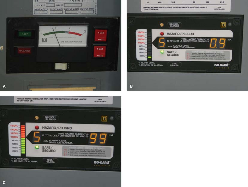 Figure 8.26. The meter of the LIM is calibrated in milliamperes. If the isolation of the power system is degraded such that >2 mA (5 mA in newer systems) of current could flow, the hazard light will illuminate and a warning buzzer will sound. Note the button for testing the hazard warning system. (A) Older LIM that will trigger an alarm at 2 mA. (B) Newer LIM that will trigger an alarm at 5 mA. (C) The LIM alarm is triggered, and the red hazard stripe is illuminated, while the number on the right shows 9.9 mA of potential current flow. |
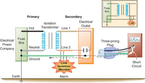 Figure 8.27. When a faulty piece of equipment is plugged into the isolated power system, it will markedly decrease the impedance from line 1 or line 2 to ground. This will be detected by the LIM, which will sound an alarm. |
The second situation involves connecting many perfectly normal pieces of equipment to the IPS. Although each piece of equipment has only a small amount of leakage current, if the total leakage exceeds 2 mA, the LIM will trigger an alarm. Assume that in the same OR there are 30 electrical devices, each having 100 μA of leakage current. The total leakage current (30 × 100 μA) would be 3 mA. The impedance to ground would still be 40,000 ohms (120/0.003). The LIM alarm would sound because the 2 mA set point was violated. However, the system is still safe and represents a state significantly different from that in the first situation. For this reason, the newer LIMs are set to alarm at 5 mA instead of 2 mA.
The newest LIMs are referred to as third-generation monitors. The first-generation monitor, or static LIM, was unable to detect balanced faults (i.e., a situation in which there are equal faults to ground from both line 1 and line 2). The second-generation, or dynamic, LIM did not have this problem but could interfere with physiologic monitoring. Both of these monitors would trigger an alarm at 2 mA, which led to annoying “false” alarms. The third-generation LIM corrects the problems of its predecessors and has the alarm threshold set at 5 mA.6 Proper functioning of the LIM depends on having both intact equipment ground wires as well as its own connection to ground. First- and second-generation LIMs could not detect the loss of the LIM ground connection. The third-generation LIM can detect this loss of ground to the monitor. In this case the LIM alarm would sound and the red hazard light would illuminate, but the LIM meter would read zero. This condition will alert the staff that the LIM needs to be repaired. However, the LIM still cannot detect broken equipment ground wires. An example of the third-generation LIM is the Iso-Gard made by the Square D Company (Monroe, NC).
The equipment ground wire is again an important part of the safety system. If this wire is broken, a faulty piece of equipment that is plugged into an outlet would operate normally, but the LIM would not alarm. A second fault could therefore cause a shock, without any alarm from the LIM. Also, in the event of a second fault, the equipment ground wire provides a low-resistance path to ground for most of the fault current (see Fig. 8-24). The LIM will only be able to register leakage currents from pieces of equipment that are connected to the IPS and have intact ground wires.
If the LIM alarm is triggered, the first thing to do is to check the gauge to determine if it is a true fault. The other possibility is that too many pieces of electrical equipment have been plugged in and the 2 mA limit has been exceeded. If the gauge is between 2 and 5 mA, it is probable that too much electrical equipment has been plugged in. If the gauge reads >5 mA, most likely there is a faulty piece of equipment present in the OR. The next step is to identify the faulty equipment, which is done by unplugging each piece of equipment until the alarm ceases. If the faulty piece of equipment is not of a life-support nature, it should be removed from the OR. If it is a vital piece of life-support equipment, it can be safely used. (Note: If a critical piece of life support equipment—like the cardio-pulmonary bypass machine—is suspected as causing the alarm, do not disconnect it until it is no longer needed.) However, it must be remembered that the protection of the IPS and the LIM is no longer operative. Therefore, if possible, no other electrical equipment should be connected during the remainder of the case, or until the faulty piece of equipment can be safely removed.
Ground Fault Circuit Interrupter
The disadvantage of using a GFCI in the OR is that it interrupts the power without warning. A defective piece of equipment could no longer be used, which might be a problem if it were of a life-support nature, whereas if the same faulty piece of equipment were plugged into an IPS, the LIM would alarm but the equipment could still be used.
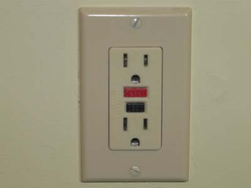 Figure 8.28. A GFCI electrical outlet with integrated test (black) and reset (red) buttons. |
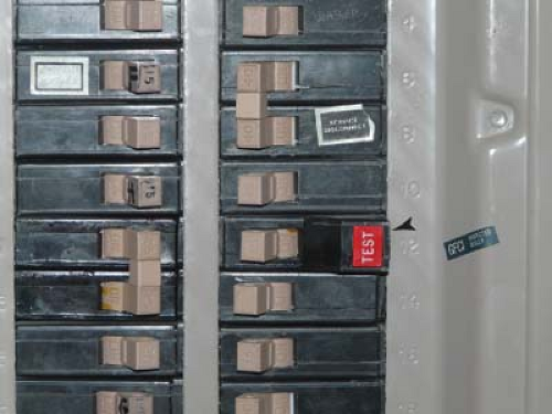 Figure 8.29. Special GFCI circuit breaker. The arrowhead points to the distinguishing red test button. |
Double Insulation
There is one instance in which it is acceptable for a piece of equipment to have only a two-prong and not a three-prong plug. This is permitted when the instrument has what is termed double insulation. These instruments have two layers of insulation and usually have a plastic exterior. Double insulation is found in many home power tools and is seen in hospital equipment such as infusion pumps. Double-insulated equipment is permissible in the OR with IPSs. However, if water or saline should get inside the unit, there could be a hazard because the double insulation is bypassed. This is even more serious if the OR has no isolated power or GFCIs.7
Microshock
Related posts:


Full access? Get Clinical Tree


